Arduino UV Meter using the UV30A Ultraviolet Sensor ElectronicsLab
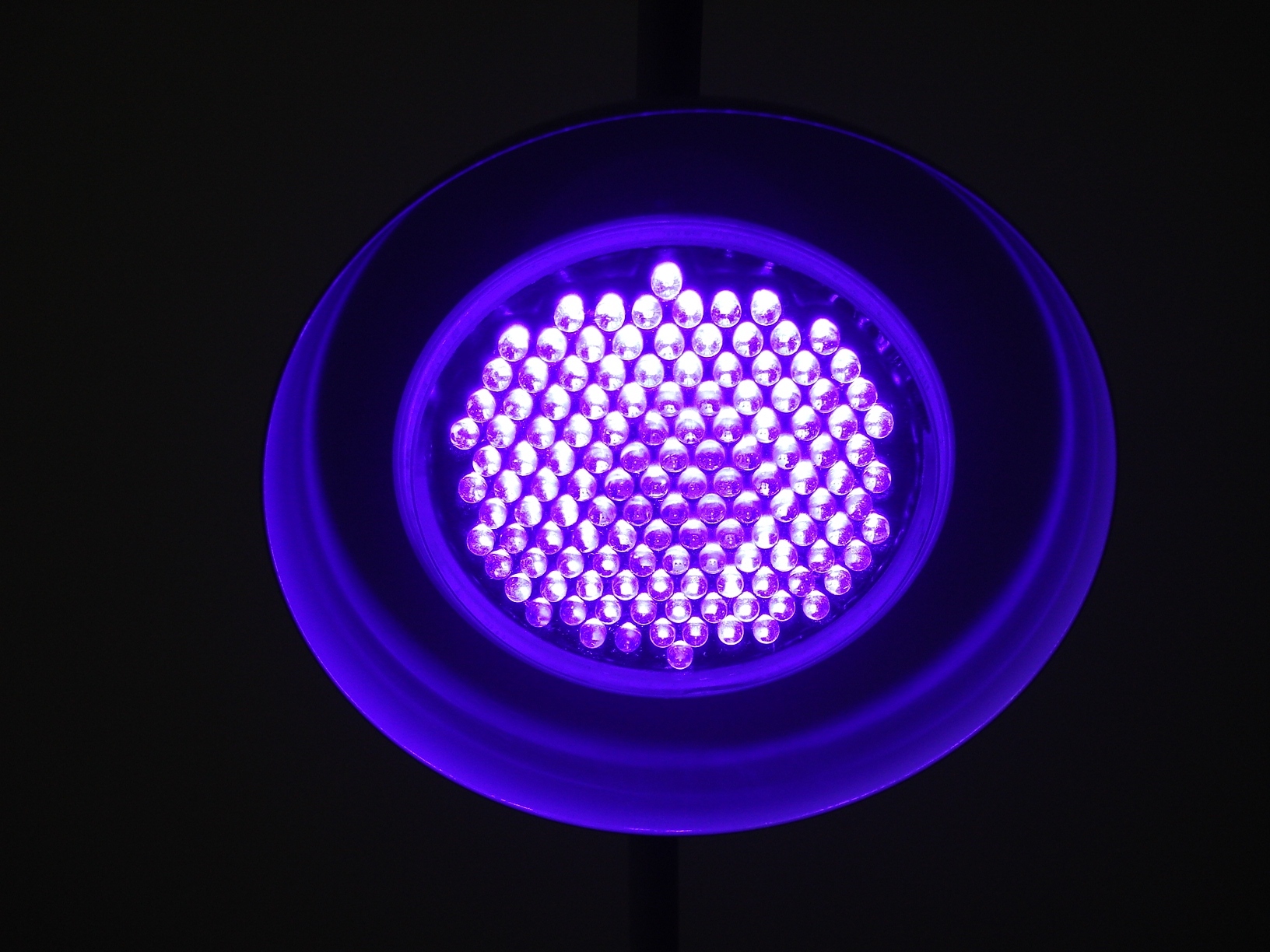
The Triad contains a 5700k white LED, a 405nm UV LED, and a 875nm IR LED mounted alongside the sensors.. The sensors are 3.3V compatible so don't use with a 5V Arduino Uno without proper conversion (use the Qwiic shield instead!). If you're using a 3.3V development platform that doesn't have a Qwiic connector,.

UV LED Meter with Arduino YouTube
How to wire UV ultraviolet LEDs experiment & tutorialSUBSCRIBE NOW FOR OTHER PROJECTS!https://www.youtube.com/channel/UCtMM9yct8wrdLEZNwLkj-2Q?sub_confirmati.
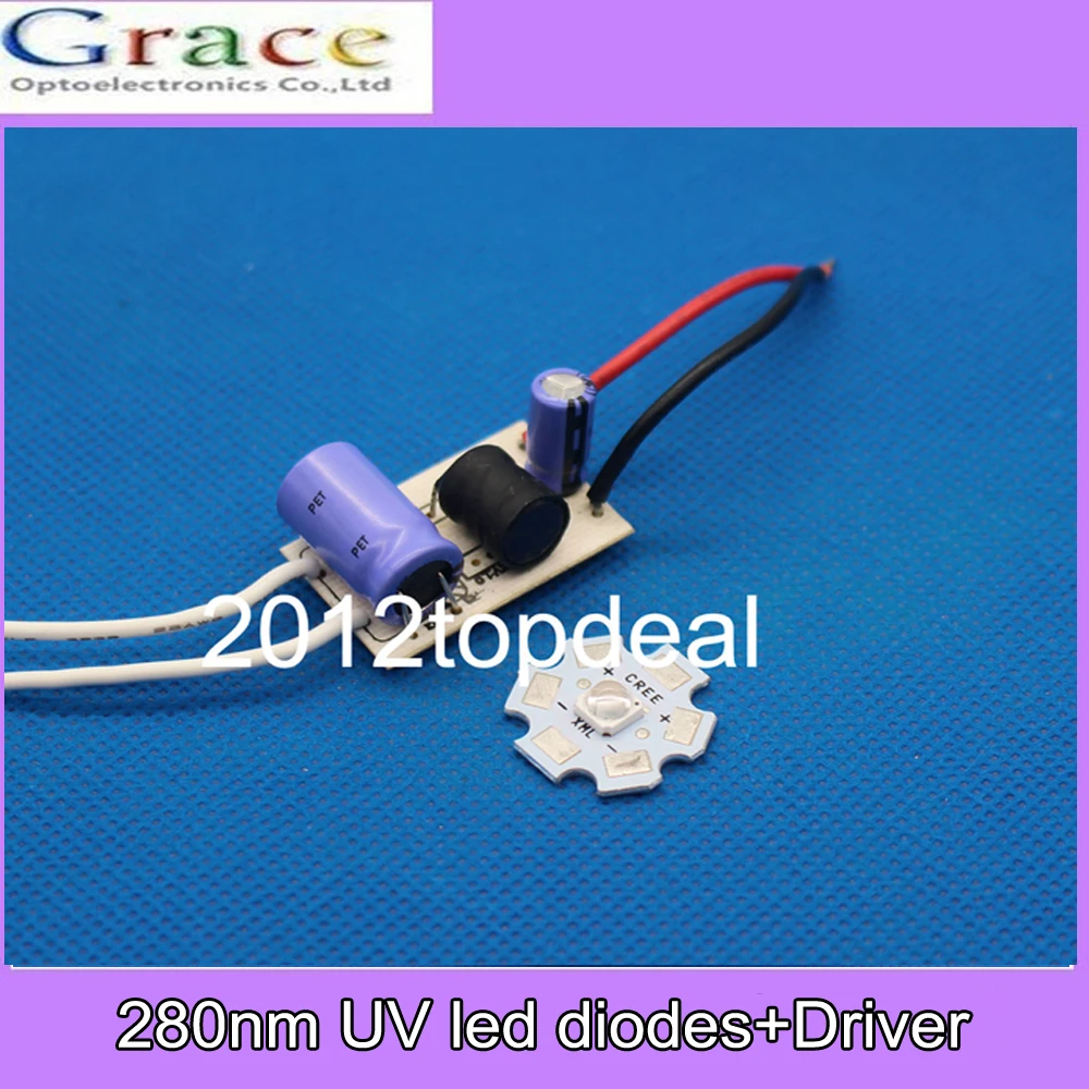
280nm UV led diodes,low wavelength Ultra Violet UV LED's with Driverin
So we recommend you pretty much just set all three channels to the same value, ranging from (0, 0, 0) to (255, 255, 255) to change the brightness of the three UV LEDs inside each 5mm x 5mm package. Technical Details UV LED Datasheet Learn Glowing Slime Lunchbox Make glowy slime for fun projects! Motorized Marble Machine
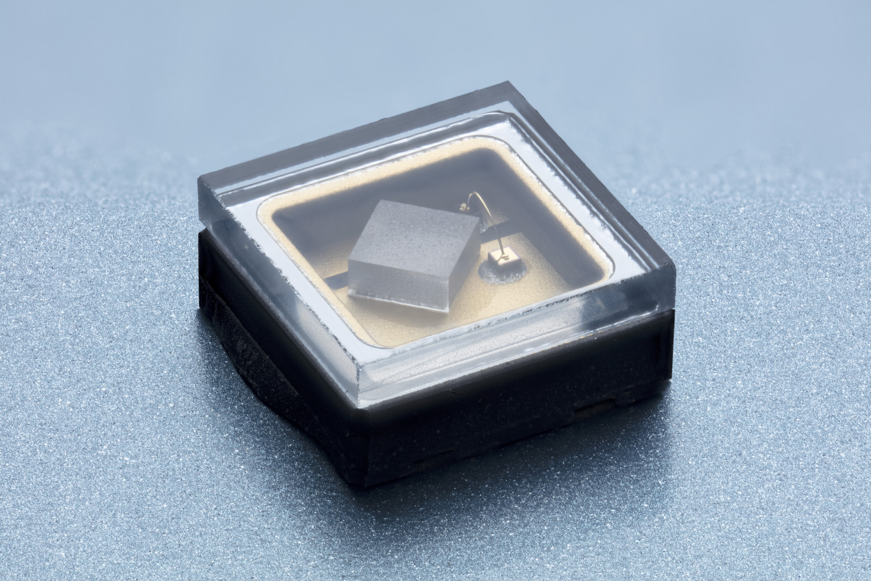
Custom UV LEDs and modules in the 320 to 233nm band
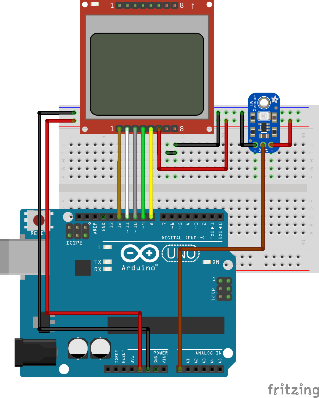
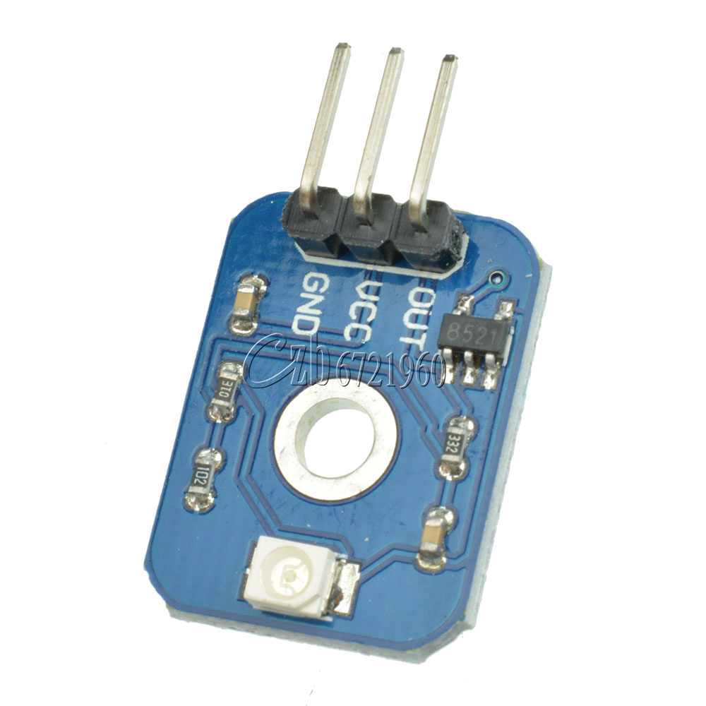
Software Apps Interfacing UVM30A UV Sensor Module with Arduino Step 1: Circuit Step 2: Code UVM30A UV Sensor Module Features Ultraviolet (UV) light is produced by sunlight. Gradual thinning of Earth's ozone layer has increased the amount of UV radiation which can lead to sunburn and other problems.
Arduino Ultraviolet Ray Module UV Sensor Module Detection Module eBay
The primary function of the robot is to disinfect a room or a flat surface using ultraviolet germicidal irradiation. The robot has ultraviolet LEDs which is responsible for killing the virus. Bio-organisms such as bacteria, viruses are known to be deactivated when exposed to UV light.

Sound Reactive UV Meter Arduino LED WS2812 RGB YouTube
Operating voltage ranges: 1.7V to 3.6V. Operating temperature ranges: -40 to +85 ºC. Built-in temperature compensation circuit. Programmable interrupt function for ALS , UVS with upper and lower thresholds. RoHS andHalogen free compliant. UVS/ALS Features. 13 to 20 bits effective resolution. Wide dynamic range of 1:18,000,000 with linear response.
VioLED International Inc.
Quick Steps. Connect Arduino to PC via USB cable. Open Arduino IDE, select the right board and port. Copy the above code and open with Arduino IDE. Click Upload button on Arduino IDE to upload code to Arduino. Move your hand in front of sensor. See the change of LED's state.
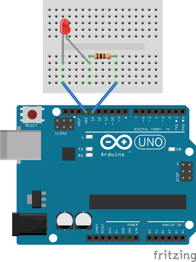
Getting Started with the Arduino Controlling the LED (Part 1)
RoboticsBD Ultimate Sensor Kit V1.0. 1. 35 projects and 37 modules for you to learn basic knowledge about Arduino.2. With an elaborately-written user manual, providing more details, clear breadboard images and schematic diagrams, and thorough wiring descriptions so you can connect the components easily.

Arduino Project LED UV exposure unit YouTube
Adafruit LTR390 UV Sensor Arduino Save Subscribe Using the LTR390 with Arduino is a simple matter of wiring up the sensor to your Arduino-compatible microcontroller, installing the Adafruit LTR390 library we've written, and running the provided example code. I2C Wiring Here is how to wire up the sensor using one of the STEMMA QT connectors.
Custom Wholesale 405nm Uv Led Light Uv Led Linear Light Machine Buy
UV TIMER arduino files.rar. Download. Add Tip Ask Question Comment Download. Step 2: PCB for UV LED Board. I decided to prepare the UV LED board in four parts of size 15X20 cm, Because it was possible to produce different size UV Exposure Box The distribution of the boards in my case, the pairs are above and the pair below, the total size of.

UV LED Digitalelectronics
Learn how to wire the UV LED to Arduino Mega in a few simple steps. The primary components for this circuit are: Arduino Mega 2560 R3 and UV LED. Drag and drop these components onto the canvas, and instantly get a list of secondary parts, wiring instructions and a test code for your circuit. Try it for free.

UV Sensor ML8511 & Arduino for UV Ray Intensity Meter
Connect the following ML8511 breakout board to Arduino: 3.3V = 3.3V OUT = A0 GND = GND EN = 3.3V 3.3V = A1 These last two connections are a little different. Connect the EN pin on the breakout to 3.3V on the breakout. This will enable the output. Also connect the 3.3V pin of the breakout to Arduino pin 1. This example uses a neat trick.
Interfacing NeoPixel LED Strip WS2812B with Arduino for Rainbow Color
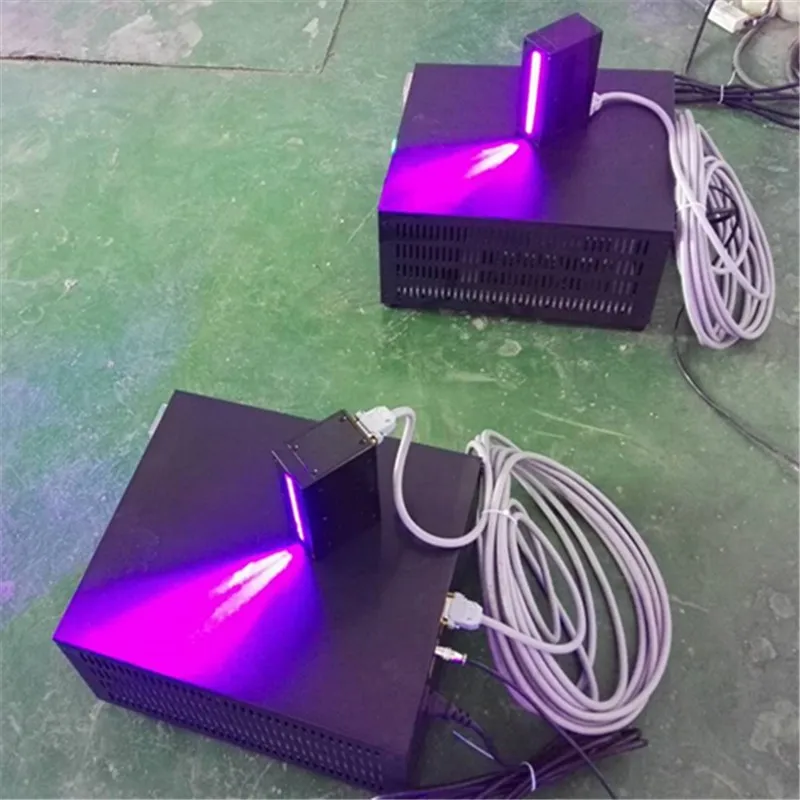
A UV light curing chamber made with an old rack, some aluminum foil, and three 50W UV LEDS. An Arduino is used as a programmable timer.. It is a commercially available chamber that uses four 30W UV LEDs as light sources. Another additional use for this chamber is found in UV glue curing, a function in which this chamber offers great.

Arduino Powered Three Color 8x8 Led Array Instructables
About LED Pinout LED includes two pins: Cathode (-) pin: needs to be connected to GND (0V) Anode (+) pin: is used to control LED's state How It Works After connecting the cathode (-) to GND: If connecting GND to the anode (+), LED is OFF. If connecting VCC to the anode (+), LED is ON.
, ,
A typical human eye will respond to wavelengths from about 390 to 700 nm. An other factor is perception of the visible spectrum, differences among gender and age. The UV photo diode will help to measure the output. dtokez:
ProjectLED UV LED Spot Light PAR164 Watts 120V AC 395nm to 405nm
The ultraviolet index is basically an international standard measurement system for measuring the strength of ultraviolet radiation at a particular place and time. For reporting the gathered information, the UV index scale is used to help determine the UV level. The following diagram shows the UV index scale: